

Vision-Guided Robotics: The Complete Guide for Integrators
- May 7
- 9 min read
Updated: May 11
A practical handbook for systems integrators planning their next vision-guided robotics deployment — the technology, the tradeoffs, and the workflow shifts that actually move pilots into production.
Table of contents
What is vision-guided robotics?
Vision-guided robotics (VGR) is any robot cell where a camera or 3D sensor closes the loop on motion. Instead of relying solely on a programmed path and rigid fixturing, the robot uses image data to locate, identify, or measure objects in real time, then adjusts its motion to act on what it sees.
That shift sounds small. In practice it changes what a cell can do. A traditional pick-and-place robot needs parts presented in a known location, with predictable orientation, every cycle. A vision-guided robotics cell handles parts that arrive in random orientations, on a moving belt, or piled in a bin. The cost of fixturing falls. The variety of parts a single cell can handle goes up. And quality control can fold into the same cycle the robot is already running.
This guide is written for integrators evaluating computer vision robotics for the first time, and for engineering leaders who have run a pilot and are deciding what it takes to put a vision-guided line into volume production.
Why integrators are betting on VGR in 2026
The economics finally add up. According to the Association for Advancing Automation (A3), companies in North America ordered 26,441 robots valued at $1.7 billion through the first three quarters of 2025 — a 6.6% increase in units and a 10.6% increase in revenue versus the same period a year earlier. A3 reports that automotive OEMs led with a 34% YoY increase in unit orders, and collaborative robots continued to capture a growing share of the market.
The vision side is growing even faster. The vision-guided robotics software market is projected to expand from $3.2 billion in 2025 to $3.82 billion in 2026, a 19.5% CAGR. North America accounts for roughly 37% of global robotic vision revenue, with the regional market valued near $1.3 billion in 2025.
The drivers behind those numbers are familiar to anyone running a plant: persistent labor shortages, pressure on cycle times, and customers who want zero-defect quality without paying for it. What is new is that the cost of getting a robot to actually see has dropped — pre-trained vision models, better depth sensors, and tighter integration tooling have collapsed what used to be a six-month custom-CV project into a deployment an integrator can scope in weeks.
2D vs 3D vision: choosing the right approach
The first decision in any VGR project is whether the application needs depth.
2D vision dominates when parts arrive on a flat plane, in known orientation, with consistent lighting. A 2D camera can locate a part to sub-millimeter accuracy, read a barcode, verify presence, or check a feature — all faster and cheaper than a 3D system. According to industry analysis, 2D vision still leads the market at roughly $2.7 billion in 2025 because so many real applications are flat-plane problems in disguise.
3D vision becomes necessary the moment depth, orientation, or pose matters. Bin picking is the canonical example: parts pile randomly, the robot needs an X/Y/Z and a tilt to grasp without a collision, and a 2D camera literally cannot see the part on top of the pile. Other 3D-mandatory applications include depalletizing mixed-SKU pallets, deformable-object handling, and assembly tasks where the mating part shifts between cycles.
A common architecture combines both. A 3D sensor locates and picks a random part; a 2D camera downstream verifies orientation before placement. This hybrid pattern shows up in automotive sub-assembly, electronics kitting, and food-and-beverage palletizing.
Key takeaway: Don't reach for 3D when 2D is sufficient. Cycle time, cost, and lighting tolerance all favor 2D for flat-plane work. Reserve 3D for applications where depth, orientation, or randomness genuinely block a 2D solution.
The vision-guided robotics tech stack
Every vision-guided cell is built from five layers. Knowing which layer your project will live or die on shapes vendor selection.
1. The sensor
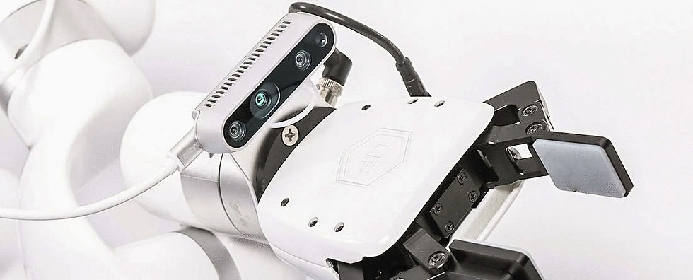
The camera or 3D sensor is the front end. Options range from monochrome 2D area-scan cameras to structured-light 3D scanners, time-of-flight depth cameras, and stereo pairs. Resolution, frame rate, depth accuracy, and field-of-view all need to map to the part you're imaging and the cycle time you have to hit.
2. The compute
Image processing happens somewhere. That can be a smart camera with on-device inference, an industrial PC mounted in the cabinet, or — increasingly — a dedicated GPU compute unit running modern vision models. Where compute lives affects latency, cost, and your ability to keep production data on-prem.
3. The software
This is the layer that has changed the most in the last 24 months. Older VGR systems required engineers to train custom models on every new part: collect images, label them, fine-tune, redeploy. Newer platforms use large pre-trained vision models that can recognize parts they have never seen, often from a natural-language prompt. The integration time savings are large.
4. The robot and end effector
Most articulated 6-axis arms can be vision-guided. The constraint is usually the controller's ability to accept dynamic pose updates and the end effector's compatibility with the part being picked. Vacuum, two-finger parallel grippers, and three-finger adaptive grippers cover most use cases; specialty tooling fills the rest.
5. The communication layer
The vision system has to hand the robot a pose. Common protocols include Ethernet/IP, PROFINET, EtherCAT, and direct TCP sockets. The payload is small — six numbers (X, Y, Z, Rx, Ry, Rz) plus a status flag — but the timing, retry behavior, and coordinate-frame definition need to be ironclad. Most production failures we see at the integrator level trace back to this layer.
The five hard problems integrators hit
Every VGR project runs into the same five problems. Plan for them before kickoff.
Lighting. The single largest cause of unreliable vision performance. Ambient light variation between shifts, reflections off shiny parts, and shadows from operators walking past the cell will break a system that demoed perfectly. Engineer the lighting environment as carefully as the optics.
Hand-eye calibration. The mathematical relationship between the camera frame and the robot frame must be precise to sub-millimeter levels in most applications. Get it wrong and every pick is offset. Get it right and the cell forgets it has a vision system. We cover this in detail in the next section.
Cycle time budget. Image acquisition, inference, pose calculation, and motion planning all consume time. A 3-second cycle target collapses fast when image processing alone takes 1.2 seconds. Profile the full loop, not just the vision step.
Edge cases the demo never hit. Demos use clean parts. Production has scratches, oil, dust, partial occlusions, parts upside-down, and parts that shouldn't be in the bin at all. Allocate time and labeled data for the failure modes you didn't see in week one.
Hand-off to operations. A line that runs three shifts a day needs to be supportable by the people on those shifts, not the engineer who built it. Document recovery procedures, make calibration repeatable without the original integrator on-site, and build dashboards a tech can read at 2 AM.
Hand-eye calibration: the make-or-break step
Hand-eye calibration is the process of solving for the rigid transform between the robot's tool frame and the camera's coordinate frame. Once solved, every pixel the camera sees can be expressed as a pose in robot coordinates and acted on directly.
It is also where most vision-guided robotics deployments lose accuracy. A peer-reviewed accuracy evaluation published in PLOS One found measurable performance differences between simultaneous and separate calibration methods, with each excelling under different rotation and translation noise profiles. The headline takeaway for integrators: there is no single "best" calibration method — the right method depends on the noise characteristics of your specific cell.
What works in practice:
Diverse pose collection. Calibrate using a wide range of robot poses and orientations, not just the four corners of the work envelope. Coverage matters more than count past about 15-20 poses.
Verification away from the calibration set. Test placement accuracy at poses you did not calibrate against. If accuracy drops, your calibration is overfit.
Re-calibration triggers. Define what events require a recalibration: camera bumped, robot serviced, end-effector swap. Bake it into the maintenance schedule.
Don't fight thermal drift. A robot that has been running for two hours has different geometry than one that just powered on. For high-precision applications, calibrate at operating temperature.
Key takeaway: Treat calibration as a first-class engineering deliverable, not a setup step. The best-trained vision model in the world cannot rescue a poorly calibrated cell.
Safety, standards, and compliance
Vision-guided cells are still robot cells. The same safety standards apply, with a few wrinkles vision adds.
The governing standard in North America is now ANSI/A3 R15.06-2025, which updates and replaces the long-running ANSI/RIA R15.06-2012 standard and harmonizes with ISO 10218-1:2025 and ISO 10218-2:2025. Part 1 covers robot manufacturers; Part 2 covers integrators and system designers — the part most VGR projects need to satisfy.
Vision-specific considerations during the risk assessment:
Vision is not a safety device. A standard 3D sensor is not safety-rated. Don't rely on it for human detection. Use safety-rated light curtains, area scanners, or safety cameras for that purpose.
Failure modes need defined responses. What does the robot do when the camera returns no detection? When the prompt returns the wrong object? Define the abort, the alert, and the recovery — and validate them.
Collaborative operation requires extra rigor. If the cell runs in collaborative mode, the speed-and-separation monitoring and power-and-force-limiting requirements in R15.06-2025 apply on top of standard guarding considerations.
OSHA does not publish robotics-specific federal standards, but the agency consistently references the ANSI/RIA R15.06 family in citations and inspections, so compliance is effectively required.
From pilot to production: a phased deployment roadmap
Most failed VGR projects fail because the pilot was scoped as the project. Production demands different things from the system than a demo does. A phased rollout gives the team room to harden each layer before exposing it to volume.
Phase 1 — Feasibility (weeks 1-2)
Image the actual parts under actual lighting. Run a basic detection or pose-estimation test using a real part sample, not stock photos. The deliverable is a binary: yes, this is solvable with vision; no, this needs different fixturing or a different approach.
Phase 2 — Pilot cell (weeks 3-8)
Build a single cell on the integrator's floor or in a sandbox area of the customer's facility. Optimize lighting, dial in calibration, profile cycle time, and stress-test edge cases. Document everything. The deliverable is a working cell hitting the customer's cycle time and accuracy targets on representative parts.
Phase 3 — Production hardening (weeks 6-12, overlapping)
This is the phase that is most often skipped. Add the dashboards, the alerting, the recovery procedures, and the operator training. Run the cell on a partial-volume basis to catch failure modes that only show up under sustained operation. The deliverable is a runbook a third-shift technician can use without calling the integrator.
Phase 4 — Scale-out (week 12+)
Replicate the cell. Each replica should be cheaper and faster than the last because you are now reusing tested patterns: the same camera mount, the same calibration procedure, the same software stack. If replication is taking as long as the original build, the pilot wasn't really productionized.
How Blue Argus fits in
This guide stays vendor-neutral by design, but it would be incomplete without explaining where our own platform fits.
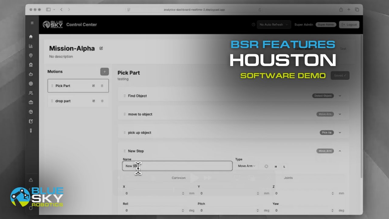
Blue Argus is a modular machine vision system for vision-guided robotics built specifically to compress the timeline between pilot and production. The core capability is what we call "Prompt to Pick Point": an integrator describes a target object in natural language via the Python SDK, and Blue Argus returns the object's 3D center point in robot coordinate space — ready to hand to the motion controller or to a path planning framework like MoveIt.
The design choices that matter for an integrator:
Zero training required for most applications. Blue Argus leverages large pre-trained vision models that recognize parts they have never seen on day one. For the vast majority of applications, the per-SKU training pipeline that historically dominated VGR project timelines is removed entirely.
Works with any robot arm exposing a Python SDK. No lock-in to a single OEM. Python sample code is included.
Modular software platform. Start with the base prompt-to-pick-point capability. Add orientation detection, enhanced depth, or faster inference as the application requires it.
No cloud dependency. The Vision SDK runs locally on the included High-Performance Compute Unit. No external GPU. No production data leaving the plant.
Available as a Suction-Enabled Kit or a General Vision Kit. The General Vision Kit works with whatever end effector the integrator already has standardized on; the Suction-Enabled Kit adds a vacuum end effector and ejector for pick-and-place and palletizing.
Kit cost depends on configuration and add-on capabilities. Contact Blue Sky Robotics for details.
Key takeaways
Vision-guided robotics is a 2D-vs-3D decision before it is anything else. Don't over-engineer; don't under-spec.
Five layers — sensor, compute, software, robot, comms — each has its own failure modes. Plan capacity at every layer.
Lighting and hand-eye calibration cause more production failures than any algorithm choice.
ANSI/A3 R15.06-2025 is the governing safety standard. Vision sensors are not safety devices.
Phase the rollout. The pilot is not the project.
Modern vision platforms with pre-trained models eliminate most per-SKU training, collapsing project timelines from months to weeks.
Ready to scope a vision-guided robotics deployment?
Request a Blue Argus demo to see how prompt-to-pick-point computer vision works on your parts. Or contact Blue Sky Robotics to talk through a specific application with our integration team.
Related reading: see our companion pillar guides on machine vision systems for industrial automation and 3D bin picking for robotic integrators, or browse the full Blue Sky Robotics blog for application-specific deep dives.