



Camera 3D: Why Your Depth Sensor Performs Differently on the Factory Floor
- Apr 6
- 5 min read
Updated: Apr 13
A camera 3D system that produced clean point clouds and reliable grasp poses during lab testing can perform very differently six weeks into production. The lighting has changed. The mounting structure vibrates slightly when adjacent equipment runs. The facility temperature drops overnight and rises again by midday. A new batch of parts arrived with a shinier surface finish than the batch used during commissioning.
None of these are catastrophic events. They are the ordinary, predictable conditions of a real manufacturing environment. But each one affects what a 3D camera sees and how accurately it reports where things are in space.
Understanding how factory environments challenge camera 3D systems, why those challenges differ by sensor technology, and what to do about them before deployment is the difference between a vision-guided robot that runs reliably across shifts and one that requires constant attention. This post covers all of it.
Why Factory Environments Challenge Camera 3D Systems
A 3D camera measures depth by comparing what it emits or observes against a known reference. Structured light cameras project a pattern and measure its deformation. Time-of-flight cameras emit infrared pulses and measure return time. Stereo cameras compare images from two offset sensors. Every one of these methods is sensitive to conditions that a production floor changes in ways a lab does not.
Ambient lighting interference- Structured light cameras project their own illumination pattern onto the scene and read how it deforms. Strong ambient light, particularly infrared-rich sources like halogen lights and direct sunlight through skylights, competes with the projected pattern and degrades the point cloud. A camera that produces excellent depth data under controlled lab lighting may miss picks or generate noisy point clouds when positioned near a bank of overhead heat lamps on a production line. Time-of-flight cameras face similar interference because they operate in the near-infrared spectrum. Choosing camera placement that minimizes direct ambient light falling within the camera's field of view is the first step, followed by selecting a camera with sufficient illumination power to overcome the ambient conditions in your specific facility.
Temperature drift- Camera 3D sensors that use structured light and time-of-flight principles are sensitive to temperature variation. As the sensor warms up from a cold start, its optical and electronic properties shift, which introduces systematic errors in the depth measurements. Research on structured light and RGB-D cameras has documented this effect as a measurable function of temperature change, producting depth errors that grow as temperature deviates from the calibration baseline. A factory that runs from 15°C overnight to 28°C by midday presents a real calibration challenge for cameras that were calibrated at a single temperature. Allowing the camera to warm up to its steady-state operating temperature before beginning production, or selecting cameras with active thermal stabilization, significantly reduces this source of error.
Vibration from adjacent equipment- Camera mounting structures that share a frame or floor with heavy machinery, presses, or conveyor drives experience vibration. For a camera 3D system mounted above a bin picking cell, that vibration introduces micro-movements between the camera and the scene during image capture that blur point cloud data and reduce the accuracy of pose estimates. The effect is subtle enough that it may not appear in static testing but becomes visible in production where adjacent machines are running. Vibration-resistant mounting hardware and isolation mounts that decouple the camera structure from the equipment structure are the practical fix.
Surface material variation- The accuracy of any camera 3D system depends significantly on what it is looking at. Highly polished metal surfaces, transparent materials, and very dark objects all produce incomplete or noisy point clouds because they reflect, transmit, or absorb the camera's illumination inconsistently. A bin of machined aluminum parts with a freshly polished surface finish from a new supplier may produce worse point cloud data than the same parts with a slightly oxidized finish from the previous supplier, even though the geometry is identical. Knowing the material properties of the parts being handled before camera selection, and testing the camera against actual production parts rather than proxy objects, prevents this class of surprise.
Matching Camera 3D Technology to Environmental Conditions
The environmental sensitivity profile of a camera 3D system varies by technology type, and matching the right technology to the specific conditions of your facility is as important as matching it to the application.
Structured light cameras produce the highest quality point clouds for stationary parts in controlled lighting. They are the right choice when the robot cell can be shielded from strong ambient light and when parts are relatively still during capture. They are the wrong choice for applications near bright overhead infrared sources or where parts are moving continuously on a conveyor.
Time-of-flight cameras bring their own near-infrared illumination, making them more robust to variable ambient lighting than passive systems. Their faster capture speed handles moving parts on conveyors better than structured light. They trade some depth precision for this speed and lighting independence, which is the right trade-off for logistics and high-throughput manufacturing applications.
Stereo cameras depend on ambient light and are most suitable for outdoor or well-lit indoor environments with consistent illumination. They are the most sensitive to lighting changes of the three technologies and should be avoided in facilities where overhead lighting varies significantly across shifts or seasons.
For any technology, IP-rated camera housings resist contamination from metal dust, cutting fluid mist, and airborne particles that are present in most machining and fabrication environments. Cameras specified at IP67 or higher maintain performance in environments where lower-rated units would be damaged within months.
Setup Practices That Preserve Camera 3D Performance Over Time
Getting a camera 3D system working at commissioning is the first problem. Keeping it working three months later is the second.
Warm-up protocol- For cameras sensitive to temperature drift, a standard warm-up period before the first production scan of the day allows the sensor to reach its steady-state operating temperature and minimizes the calibration error introduced by thermal expansion. The specific warm-up time varies by camera model, but 15 to 30 minutes is a reasonable baseline for structured light systems in variable-temperature environments.
Regular calibration checks- Hand-eye calibration aligns the camera's coordinate frame with the robot's. Thermal expansion of the mounting structure, gradual mechanical wear, and minor vibration-induced shifts can move this relationship over time without any obvious hardware event. Scheduling monthly calibration verification catches drift before it degrades pick accuracy enough to cause production stoppages.
Shielding and controlled illumination- A simple enclosure or hood around the camera's field of view that excludes direct overhead light reduces ambient interference significantly without requiring a camera upgrade. For facilities with strong ambient infrared sources, this is often the most cost-effective first step.
Pairing Camera 3D Performance with the Right Robot
A camera 3D system that holds up in your production environment is only half the cell. The robot arm that acts on its output needs to match the payload and reach requirements of the application.
For light bin picking and tabletop inspection where a compact camera 3D setup handles small parts, the UFactory Lite 6 ($3,500) is the entry point. For production-level bin picking and machine tending where camera 3D performance needs to be stable across multiple shifts, the Fairino FR5 ($6,999) and Fairino FR10 ($10,199) handle the payload requirements with the repeatability that production-level applications demand. For heavier applications where a camera 3D system monitors a wide work envelope for palletizing and depalletizing, the Fairino FR16 ($11,699) and Fairino FR20 ($15,499) cover the payload range.
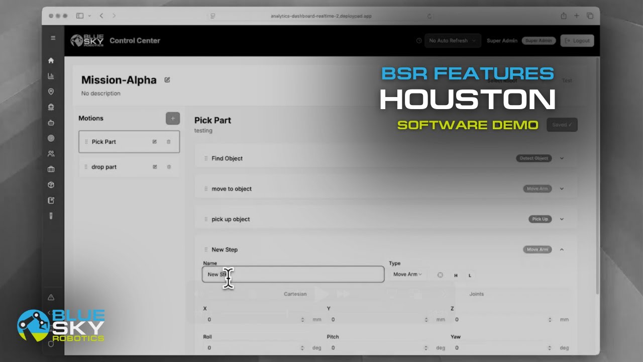
Blue Sky Robotics' automation software connects the camera 3D output to robot motion in a single integrated platform, reducing the number of interfaces where environmental degradation creates unexpected system behavior.
Use the Cobot Selector to match the right arm to your application, or book a live demo to see a camera 3D-guided robot cell running under production conditions before committing to hardware. To learn more about computer vision software visit Blue Argus.


